- Volumes 84-95 (2024)
-
Volumes 72-83 (2023)
-
Volume 83
Pages 1-258 (December 2023)
-
Volume 82
Pages 1-204 (November 2023)
-
Volume 81
Pages 1-188 (October 2023)
-
Volume 80
Pages 1-202 (September 2023)
-
Volume 79
Pages 1-172 (August 2023)
-
Volume 78
Pages 1-146 (July 2023)
-
Volume 77
Pages 1-152 (June 2023)
-
Volume 76
Pages 1-176 (May 2023)
-
Volume 75
Pages 1-228 (April 2023)
-
Volume 74
Pages 1-200 (March 2023)
-
Volume 73
Pages 1-138 (February 2023)
-
Volume 72
Pages 1-144 (January 2023)
-
Volume 83
-
Volumes 60-71 (2022)
-
Volume 71
Pages 1-108 (December 2022)
-
Volume 70
Pages 1-106 (November 2022)
-
Volume 69
Pages 1-122 (October 2022)
-
Volume 68
Pages 1-124 (September 2022)
-
Volume 67
Pages 1-102 (August 2022)
-
Volume 66
Pages 1-112 (July 2022)
-
Volume 65
Pages 1-138 (June 2022)
-
Volume 64
Pages 1-186 (May 2022)
-
Volume 63
Pages 1-124 (April 2022)
-
Volume 62
Pages 1-104 (March 2022)
-
Volume 61
Pages 1-120 (February 2022)
-
Volume 60
Pages 1-124 (January 2022)
-
Volume 71
- Volumes 54-59 (2021)
- Volumes 48-53 (2020)
- Volumes 42-47 (2019)
- Volumes 36-41 (2018)
- Volumes 30-35 (2017)
- Volumes 24-29 (2016)
- Volumes 18-23 (2015)
- Volumes 12-17 (2014)
- Volume 11 (2013)
- Volume 10 (2012)
- Volume 9 (2011)
- Volume 8 (2010)
- Volume 7 (2009)
- Volume 6 (2008)
- Volume 5 (2007)
- Volume 4 (2006)
- Volume 3 (2005)
- Volume 2 (2004)
- Volume 1 (2003)
• A lab-scale combustor-style regenerator was designed by scaling-down an industrial regenerator.
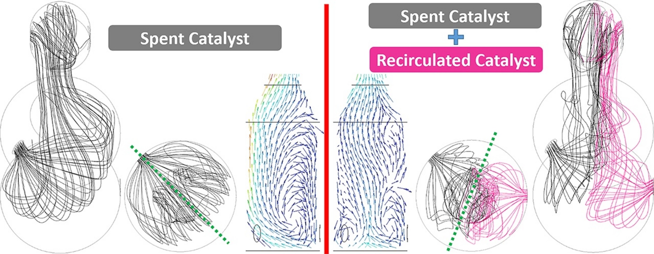
• The gas–solid flow pattern within the regenerator was scrutinized using CFD simulations.
• Effects of recirculated catalyst, superficial air velocity and catalyst mass flux were studied.
To investigate the gas–solid flow pattern of a combustor-style fluid catalytic cracking regenerator, a laboratory-scale regenerator was designed. In scaling down from an actual regenerator, large-diameter hydrodynamic effects were taken into consideration. These considerations are the novelties of the present study. Applying the Eulerian–Eulerian approach, a three-dimensional computational fluid dynamics (CFD) model of the regenerator was developed. Using this model, various aspects of the hydrodynamic behavior that are potentially effective in catalyst regeneration were investigated. The CFD simulation results show that at various sections the gas–solid flow patterns exhibit different behavior because of the asymmetric location of the catalyst inlets and the lift outlets. The ratio of the recirculated catalyst to spent catalyst determines the quality of the spent and recirculated catalyst mixing and distribution because the location and quality of vortices change in the lower part of the combustor. The simulation results show that recirculated catalyst considerably reduces the air bypass that disperses the catalyst particles widely over the cross section. Decreasing the velocity of superficial air produces a complex flow pattern whereas the variation in catalyst mass flux does not alter the flow pattern significantly as the flow is dilute.

